Este fue el primer intento, bastante mugriento, aunque funcionó bien de todos modos.
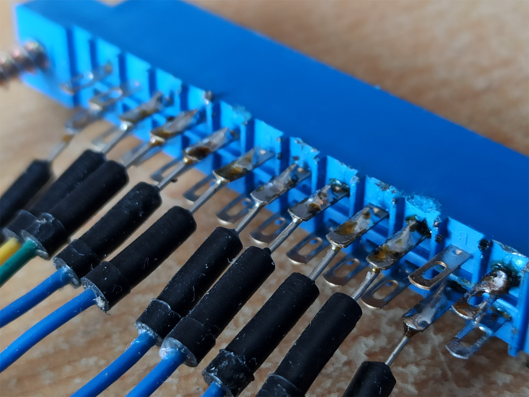
Después conseguí hacerlo sin quemar el soporte de plástico.

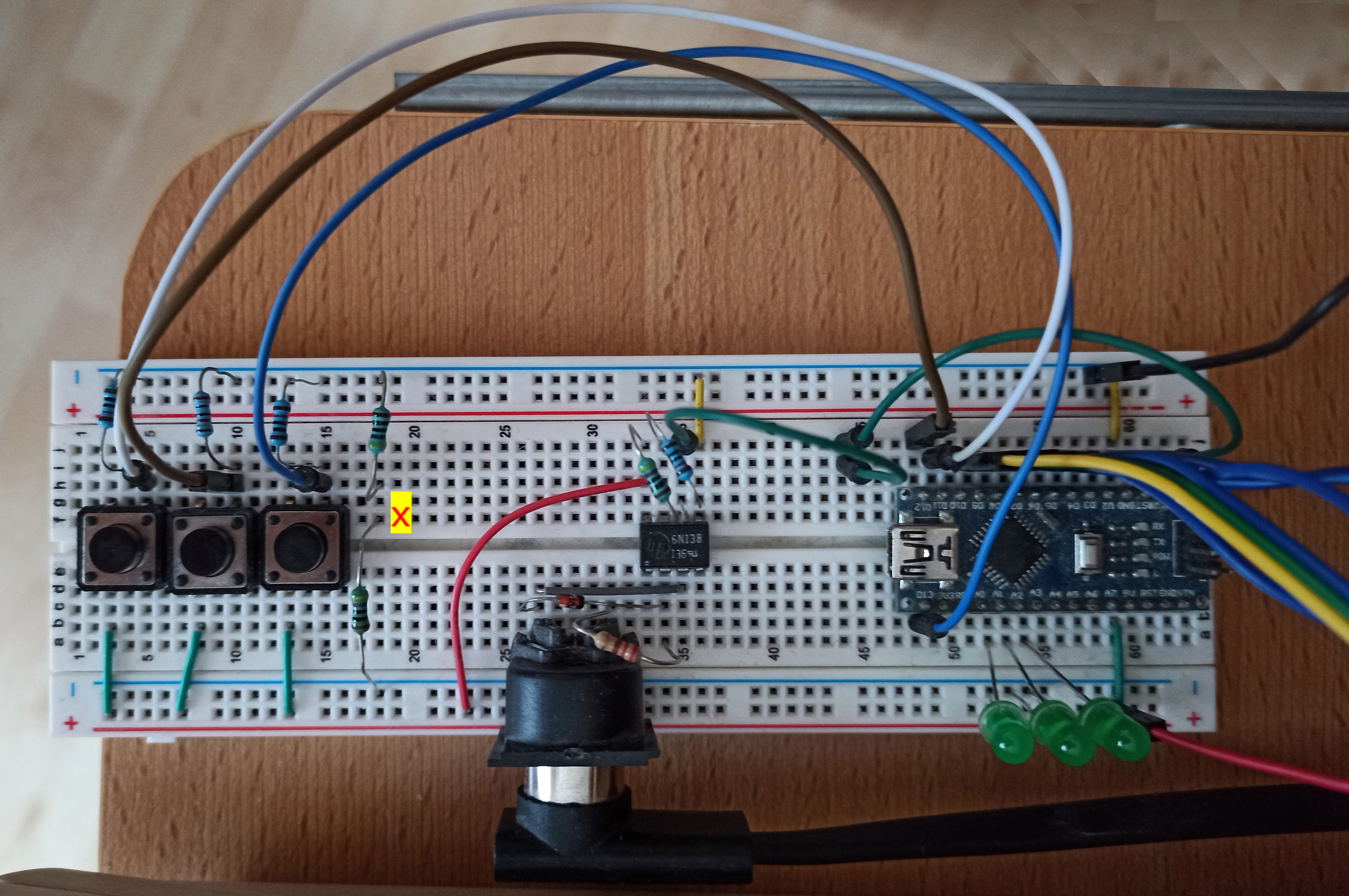
And so looks it like without the puhs buttons.
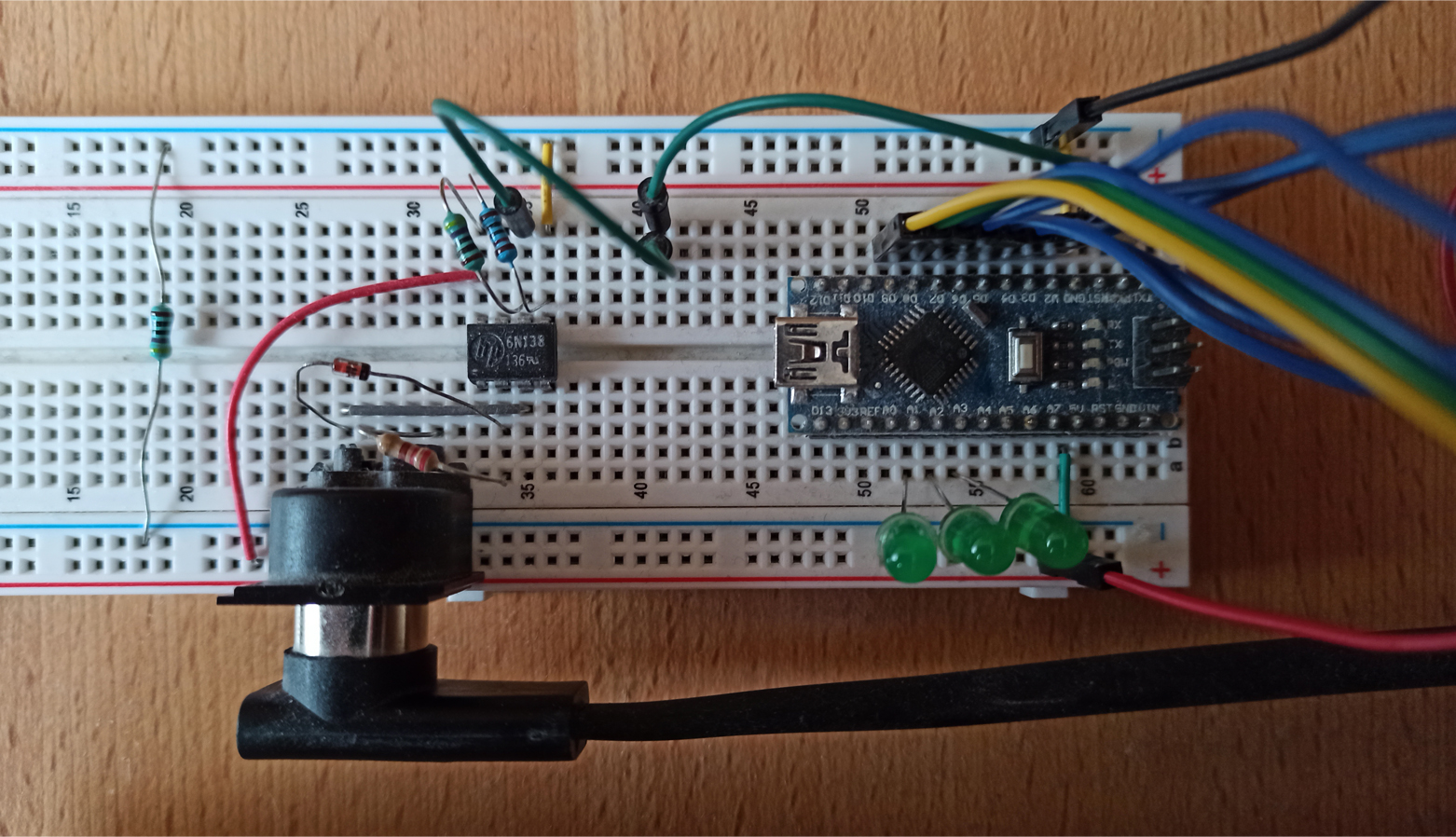
There
are three functions you can control with control changes from your MIDI
controller or with push buttons from the Arduino circuit.
1.
Switches ciclicaly among the 6 modes: 1 > 2 > 3 > 4 > 5 > 6 > 1. This is
CC #97 or the push button connected by the white wire.
2.
Shifts ciclicaly the keyboard's split point, one octave to the right: C4 >
C5 > C6 > C2 > C3 > C4 [verificar]. Once you reach the rightmost point, the
next position will be the leftmost one again. This is CC #96 or the brown
wire.
3. Toggles left / right the
two parts of the split keyboard. This is CC #66 or the blue wire.
If
you want to use other control changes, you can search for 97, 96 and 66
in the Arduino sketch and change them for other values.
----------------------------------------------------------------------
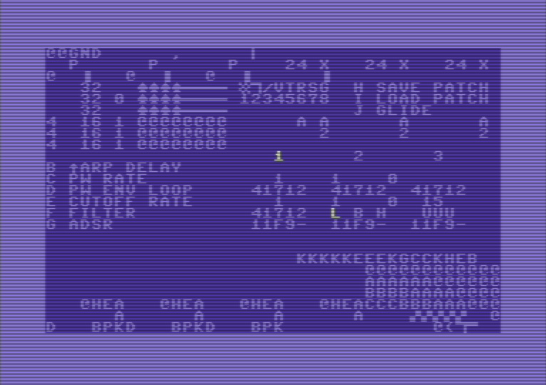
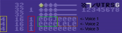
The numbers 1, 2 and 3 in the middle of the screen
stand for the three voices.
![]()
The number highlighted in white is the voice currently
selected, which can be changed by pressing the
keys 1, 2 and 3. Some
parameters can be edited only for one voice each time, so you have to select
first the voice you want to edit. These parameters are PW ENV LOOP (option
D), ADSR (option G) and the
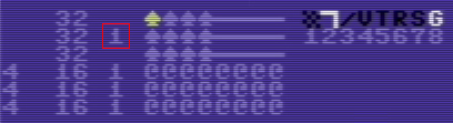
oscillator tuning, located top right:
![]()
With the cursor
up/down key you can increase or decrease
the pitch by
12 semitones (one octave) and
with the right/left key 1
semitone more or less.
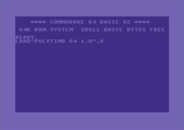
This
main
screen contains the only menu you'll use to edit
all settings. At this point, you can perform a first sound test: by
pressing the space bar key,
you'll enter the play mode. You'll see some charachters rapidly changing
on screen, and if you press keys on your MIDI keyboard, you should be able
to hear the notes. The default mode is polyphonic, so there must be possible
to play up to three notes at the same time. By pressing the
Return key you'll be back at the
edit mode; any character should stop changing on the screen.
By pressing the
keys A to K you can access the following options.
Only B to J are
visible on the menu.
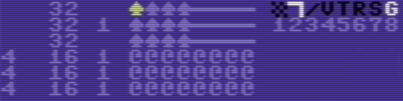
| A |
Wave tables and arpeggios editor |
This is the most complex section, containing several parameters
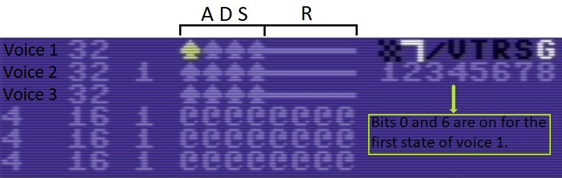
explained below. The three upper rows
are the waveforms editor, wich basically represents a sequence of four states in the registers 54276, 54283 and 54290. These SID's registers determine the oscillators' waveforms, as well as the synchronization and the ring modulation effects and the gate state. Each character stands for a state of the register at a time unit. All 8 bits can be switched on/off independently.
The numbers 1 to 8 stand for the keys you have to press, but when I refer to bits they are numbered from 0 to 7 and from right to left.
The first 4 states
are
swept in a loop from left to right during the ADS phase (when you
press a key in the MIDI keyboard) and the last 4 states
are swept
the same way in the R phase (when you release the key and the sound
starts to fade out). By combining different waveforms within the
same phase, distorted and metallic sounds can be generated.
The
three lower rows
are the arpeggios editor. |
|||||||||||||||||||||||||||||||
| B |
Arpeggios speed |
Sets the speed at wich arpeggios are swept. Arpeggios can be set as fixed in the arpeggios editor or as pseudochords in real time, as you play several notes simultaneously (keyboard mode 3 and mode 4). Valid values are in the range from 1 to 128. | |||||||||||||||||||||||||||||||
| C |
Pulse width sweep speed, square LFO on/off |
This synthsizer uses two
software generated LFO to modulate the cut off frequency and the
square waveform pulse width, respectively. Although the SID can use
the third oscillator's output to hardware generate an LFO, I left
out this built-in LFO, as it works at the price of giving up
the sound of voice 3.
Polytimb
64
actually features three independent LFOs to modulate the PW in each
of the three voices, but for the time being I'm using the same LFO
for
the square waveform of all
voices.
The first
value determines the speed of the ascending sweeping through a PW
defined range (see option D). The second value does the same for the
descending sweeping. This is like routing the PW through a LFO.
|
|||||||||||||||||||||||||||||||
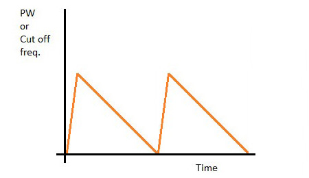
| D |
Pulse width envelope/loop |
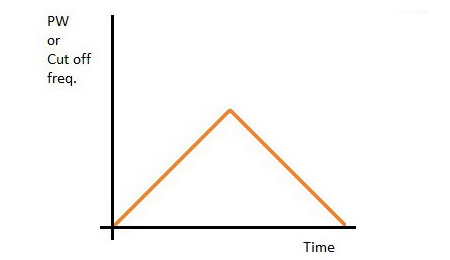
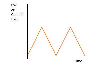
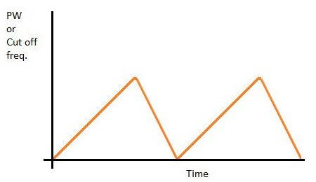
This controls the LFO as
well as a kind of primitive envelope for the PW by determining the
starting, highest and lowest PW levels (first, second and third
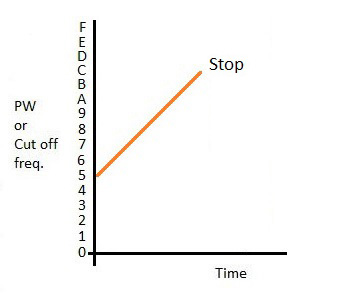
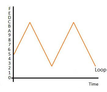
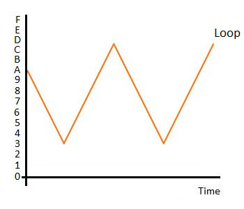
digits, respectively). The fourth digit sets the initial direction
of the PW sweep (1 = ascending, 0 = descending) and the fifth digit
sets if the PW stops sweeping once it reaches the lowest/highest
point for the first time (0), if it stops after reaching a second
lowest/highest point (1), or if it keeps on sweeping up and down
indefinitely between the lowest and highest levels.
For the
first three digits the range is between 0 and F: for the sake of
simplicity only the most significant byte of the PW can be selected
by the user. However, the PW sweeps all along the least significant
byte
(at the speed defined in option C).
In this
settings, the values are entered with
keys 0 to 9 and
A to F, shifting the
selected digit left and right with the
cursor keys. Hitting the
Return key confirms the
selected values and T
copies the selected values to the PW envelopes of all voices.
|
|||||||||||||||||||||||||||||||
| E |
Filter cut off sweep speed, square LFO on/off, filter resonance |
This is the same as option C but for the filter cut off frequency. In addition to the three values explained in (C) you have to enter here a fourth value between 0 - 15 for the filter resonance. For instance, "1,1,0,15" stands for 1 sweep speed up, 1 for sweep speed down, no square LFO and 15 (maximal) resonance. | |||||||||||||||||||||||||||||||
| F |
Filter cut off envelope/loop |
Same as option D, but for modulating the filter cut off frequency. Since the SID cut off frequency is 11 bits long, the maximal value you can enter here for the first three digits is 7 instead of F. | |||||||||||||||||||||||||||||||
| G | Volume ADSR |
This is the amplitude
envelope generator. Unlike options D and E, this is a hardware
feature of the SID: registers 54277 (attack/sustain) and 54278
(sustain/release) for oscillator 1, registers 54285 and 54286 for
oscillator 2, and registers 54291 and 54292 for oscillator 3. The
values are entered by pressing the
keys 0 to F; the left and
right cursor keys shift the selected digit, the
Return key confirms the entered values and the
T key copies them to all three voices. |
|||||||||||||||||||||||||||||||
| H |
Save patch |
||||||||||||||||||||||||||||||||
| I |
Load patch |
||||||||||||||||||||||||||||||||
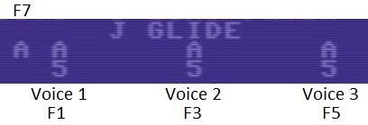
| J | Glide speed |
This sets how fast (1 =
fastest, 255 slowest) a note's pitch increases or decreases when you
press a key on the keyboard. Three values separated by comma must be
entered, one for each voice. Very slow glide speeds let hear "steps"
along the pitch variation, but for most "normal" speeds you'll hear
a continuous, smooth glide.
In order to the glide
effect to be effective, it has to be set to one of the three ON
modes. With the keys F1
(voice 1), F3 (voice 2) and F5
(voice 3) you can sequentially select:
 |
|||||||||||||||||||||||||||||||
| K |
Wave tables speed |
Enter a delay value for each voice, separated by comma, to determine how fast the sequence of waveforms is read in a loop (the higher, the slower). More about this here. | |||||||||||||||||||||||||||||||
| L | Enter POKEs manually | [Funciona, pero lo vamos a dejar en blanco.] |
Once you press the A key in the main menu, you enter
this area, with the cursor on the middle of the top row.
Here you can edit a number of paramaters with the
following keys:
With the
following keys you can switch on and off which voices routed through the filter
and what type of filters you use:
WIn the example below, the low pass filtered is selected, voices 1 (U) and 2 (U) are routed through the filter while voice 3 (@) is bypassed.
![]()
The most frequent problem I had were notes that didn't stop to sound when I released the key on the piano. And the most common cause behind this problem were low batteries in the MIDI controller. It's advisible to use a power supply or make sure that batteries are fully loaded.
Check that all wires and parts are properly soldered or inserted in the breadboard.
To pin down some problems you can check the board as explained before. Any time you press a key, the Arduino built in LED should briefly blink, and the same should happen when you release the key. If this is not the case, something went wrong with the sketch upload or some parts aren't properly connected in the circuit. If the LED blinks but the C64 doesn't produce any sound, then the problem lies somewhere between Arduino and the C64.